Bevel Gears
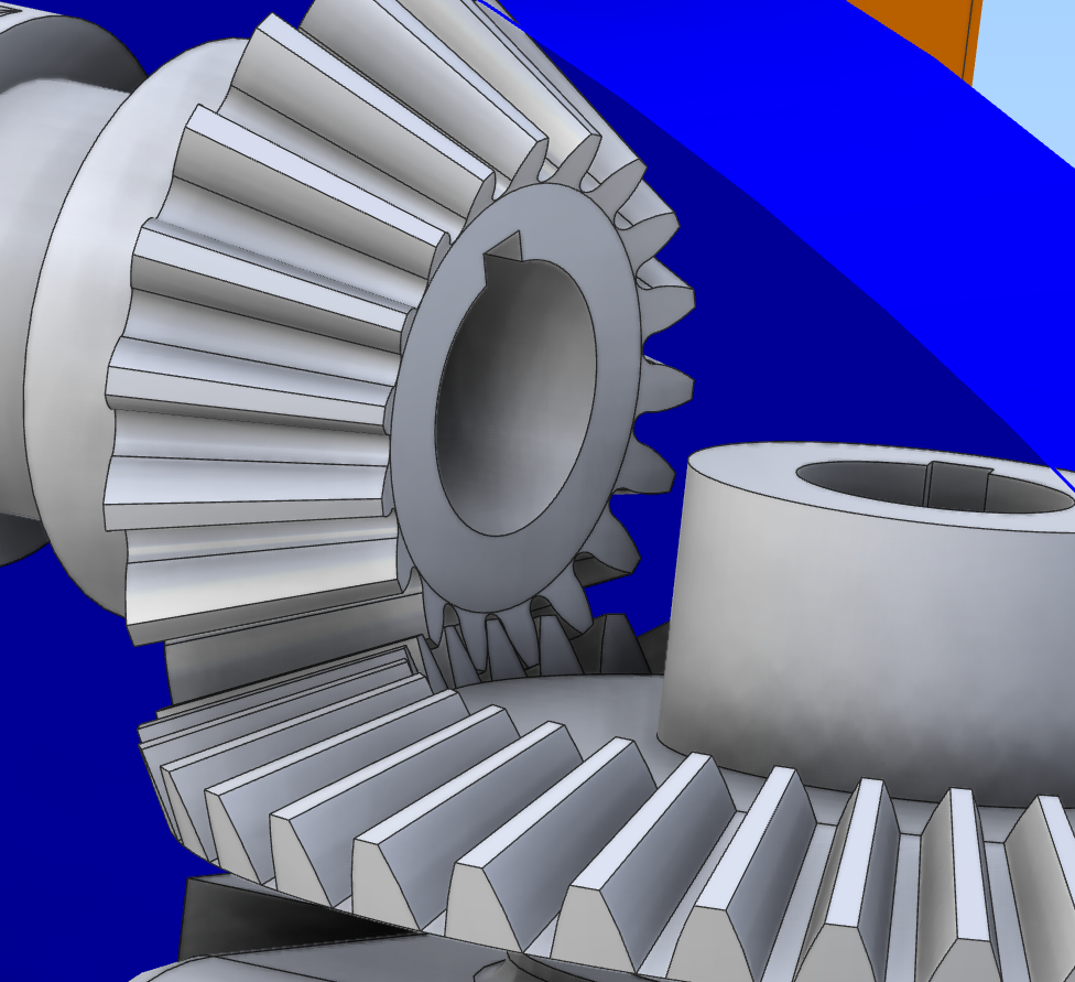
This tool can be used to develop models of straight tooth Standard and Gleason bevel gears.


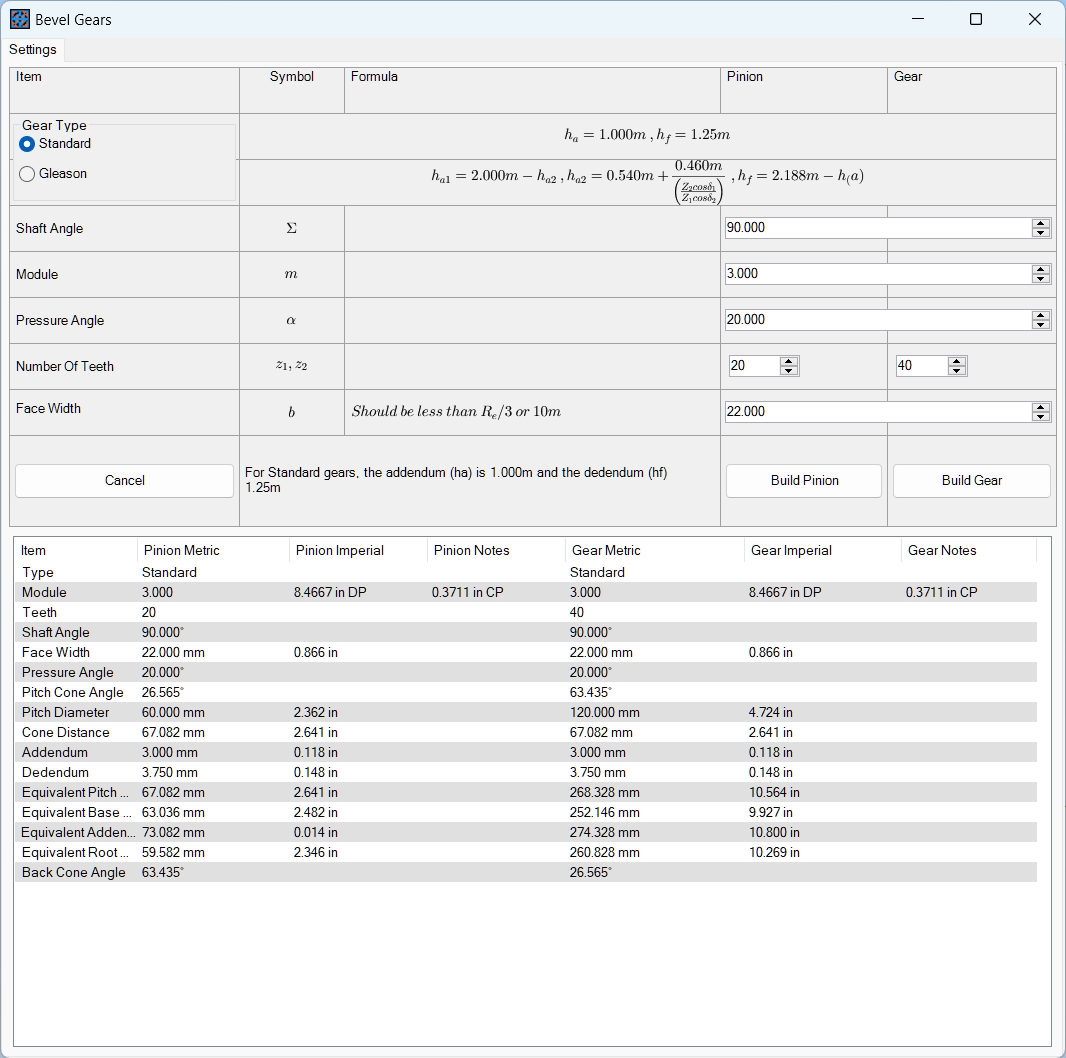
Usage of the tool requires just 7 parameters be entered by the user:
Gear Type: Standard or Gleason. The essential difference between these two types is in the dimensions of the tooth Addendum (that part of the tooth above the pitch circle diameter) and the Dedendum (that part of the tooth below the pitch circle diameter).
Details of the calculations used by the tool are provided:
Shaft Angle: This is the included angle of shafts mounting the Pinion and Gear wheel. Whilst this control is limited to 180°, there are other practical limits to what is acceptable here; in general terms, angles between 60° and 120° should produce acceptable gears but also depending on the relative number of teeth.
Module: This essentially determines the size of the gear teeth. For convenience, the Imperial equivalent of the metric module size is provided in the details table.
Pressure Angle: Commonly used pressure angles are 14.5°, 20° and 25°. Other angles can be defined here if required.
Number of Teeth: Set these controls to the desired number of teeth on the Pinion and Gear respectively. Note that there is an interdependency between the Pinion and Gear dimensions so having set all parameters, BOTH pinion and gear parts should be generated before making any further changes.
Face width: This sets the width of the generated gear tooth. There are practical limits to the face width. It certainly can not exceed the Cone Distance (Re) and is generally limited to Re/3 or 10 times the module size.
Build Pinion, Build Wheel buttons: These will take the parameters set and pass the details to Alibre. The Bevel Gear template file has two sketches:
Sketch<1> Is used to develop the gear blank profile as a rotation of this sketch.
Sketch<2> Is used to develop the space between the gear teeth and thus the tooth profile. This sketch is developed on the Back Cone Plane used by a Loft Cut feature from the sketch to the Pitch Apex sketch point. The location and angle of the Back Cone Plane is calculated by the tool.
The tooth flanks are made up of an involute curve (a spline in Sketch<2>) and relief curves at the tooth base if there is sufficient space between the tooth base circle and the root circle.
A simple circular feature pattern is used to pattern the loft cut to develop the required number of teeth.
Details of the calculations used to generate the gear profiles can be found here..