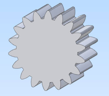
Profile Shifted External Spur Gears

Profile Shifted Spur gears feature profile adjustment to allow for variations in design such as a non-standard centre distance. The table below provides an example of a spur gear pair and the calculations used to derive the design values.
The following parameters are required as inputs:
Module
Pressure Angle. Usually one of 14.5°, 20° or 25°.
Number of Teeth, Pinion and Gear
Working Centre Distance.
Coefficient of Profile Shift, Pinion and Gear. Note that the Sum Coefficient of Profile Shift is a calculated value; it is the distribution of this value between Pinion and Gear that is required as a user input.
Profile Shifted Spur Gear
No. | Item | Symbol | Formula | Pinion | Gear |
|---|---|---|---|---|---|
1 | Module | Design Parameter | 3 | ||
2 | Pressure Angle | Design Parameter | 20° | ||
3 | Number of Teeth | Design Parameter | 12 | 24 | |
4 | Working Centre Distance | Design Parameter | 56.500 | ||
5 | Coefficient of Profile Shift | Design Parameter Note #1 | 0.6 | 0.36 | |
6 | Sum Coefficient of Profile Shift | 0.960 | |||
7 | Centre Distance (Standard) | 54.000 | |||
8 | Involute Function | 0.014904 | |||
9 | Working Involute Function | 0.034317 | |||
10 | Working Pressure Angle | 26.0888° | |||
11 | Centre Distance Increment Factor | 0.83333 | |||
12 | Pitch Diameter | 36.000 | 72.000 | ||
13 | Base Diameter | 33.8289 | 67.6579 | ||
14 | Working Pitch Diameter | 37.667 | 75.333 | ||
15 | Addendum | 4.420 | - | ||
- | 3.700 | ||||
16 | Dedendum | 1.950 | - | ||
- | 2.670 | ||||
17 | Whole Depth | 6.370 | |||
18 | Outside Diameter | 44.840 | 79.400 | ||
19 | Root Diameter | 32.100 | 66.660 | ||
20 | Radial/Total Contact Ratio | Note #2 | 1.202 | ||
- #1
The values for are manually assigned and normally sum to equal the Sum Coefficient of Profile Shift (Item 6).
- #2